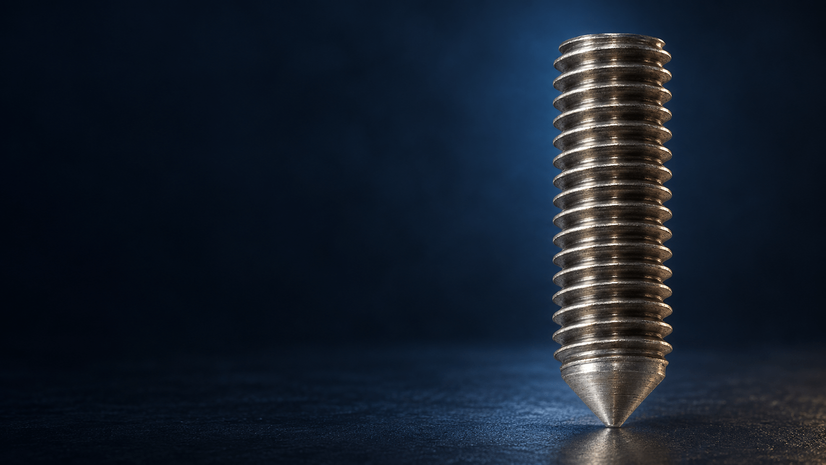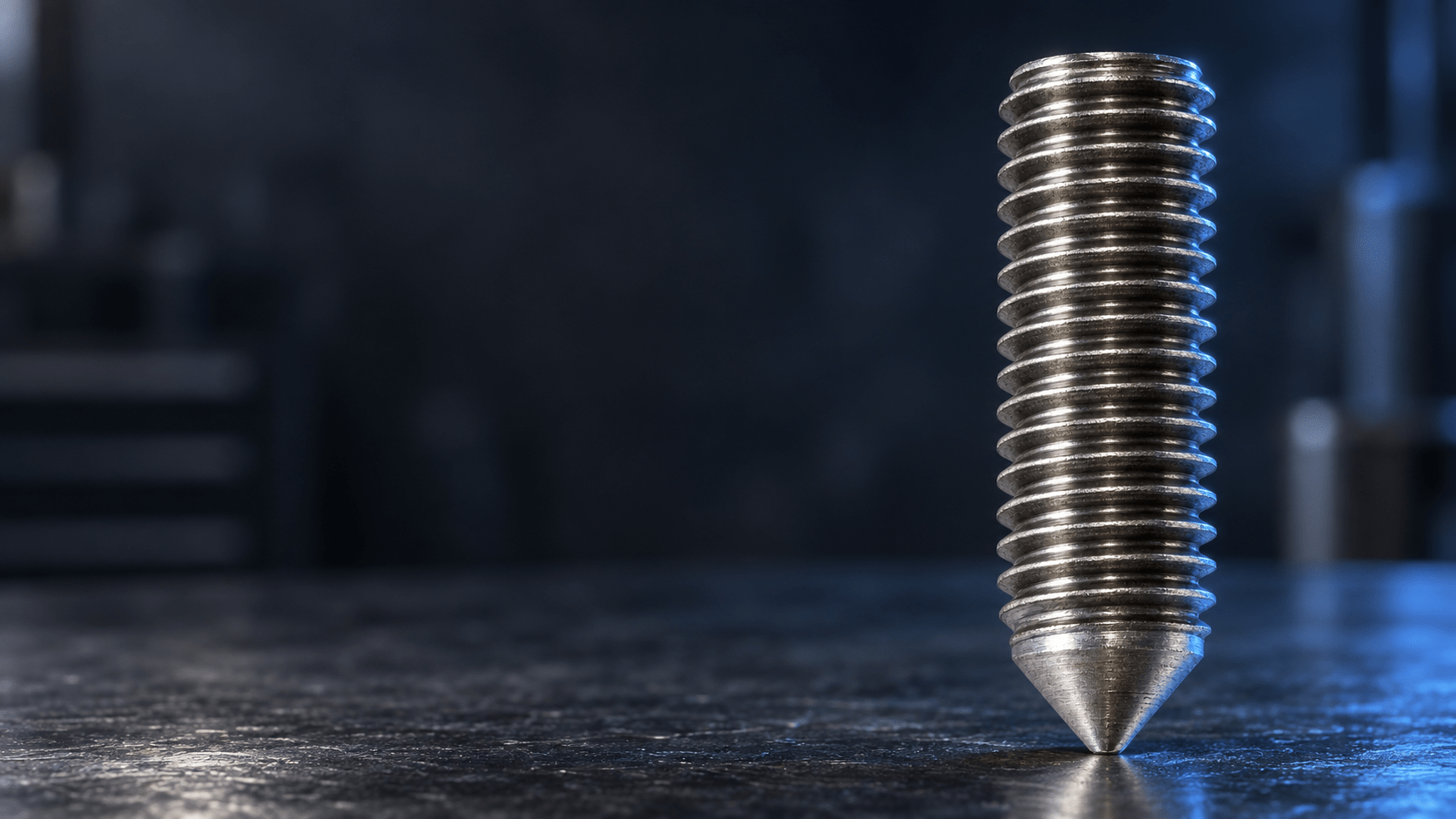
FULLY THREADED
STUDS
FD
CONTINUOUS THREAD.
WELDABLE FASTENING.
| Welding process | Drawn arc welding |
|---|---|
| Thread sizes | M6, M8, M10, M12, M16, M20 |
| Design | Continuous external thread |
| Length l₂ | 15–100 mm according to the data sheet; size/length combinations on request |
| materials | Steel 4.8 Stainless steel A2-50 |
| Availability | On request |
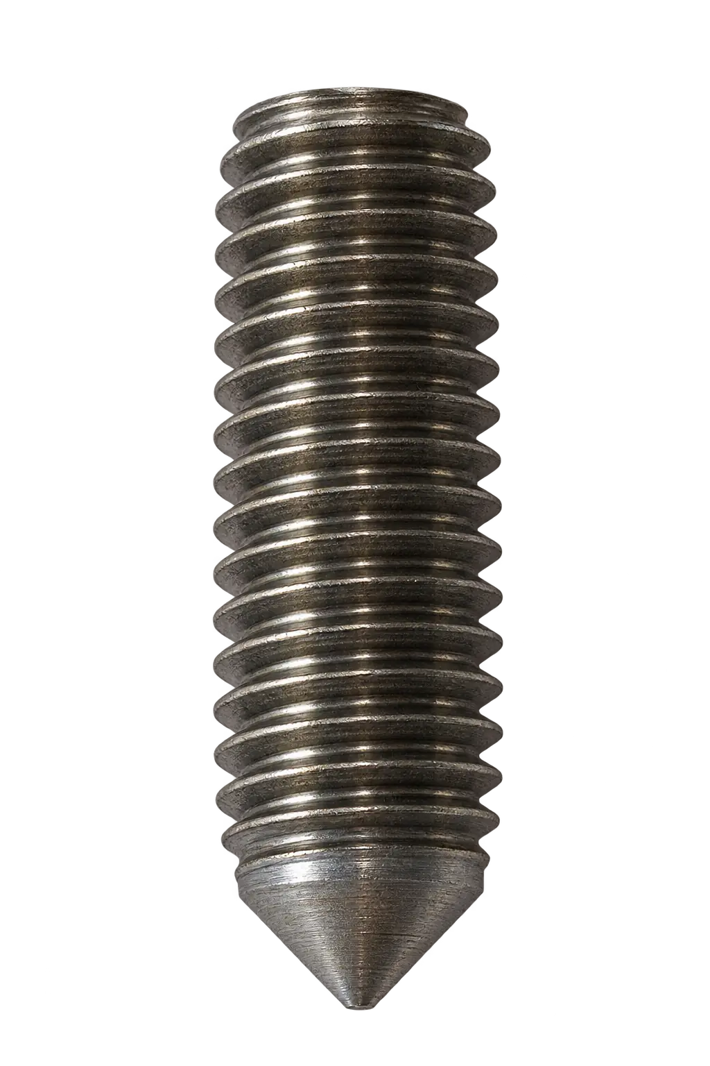
FD threaded studs from M6 to M20.
The product source lists steel 4.8 and stainless steel A2-50 and processing in manual and fully automatic welding processes. Dimensions d₃ and h₄ describe the welding area after welding; their values are listed in the dimensional table.
FD: dimensions
and materials

| d₁ | l₂ | d₃ | h₄ | Angle ±7° |
|---|---|---|---|---|
| M6 | 15–100 mm* | 8,5 | 4 | 140° |
| M8 | 11 | 4 | ||
| M10 | 13 | 4 | ||
| M12 | 16 | 5 | ||
| M16 | 21 | 7 | ||
| M20 | 26 | 7 |
*The data sheet specifies the range 15–100 mm but does not assign individual lengths to thread sizes. Please enquire about available combinations.
| Steel | 4.8 |
|---|---|
| Stainless steel | A2-50 |
For your enquiry: specify thread size, required length l₂, material and quantity.
FD threaded studs
for industrial fastening tasks
Structural steelwork

Vehicle manufacturing

Mechanical engineering

Plant engineering

Rail vehicles
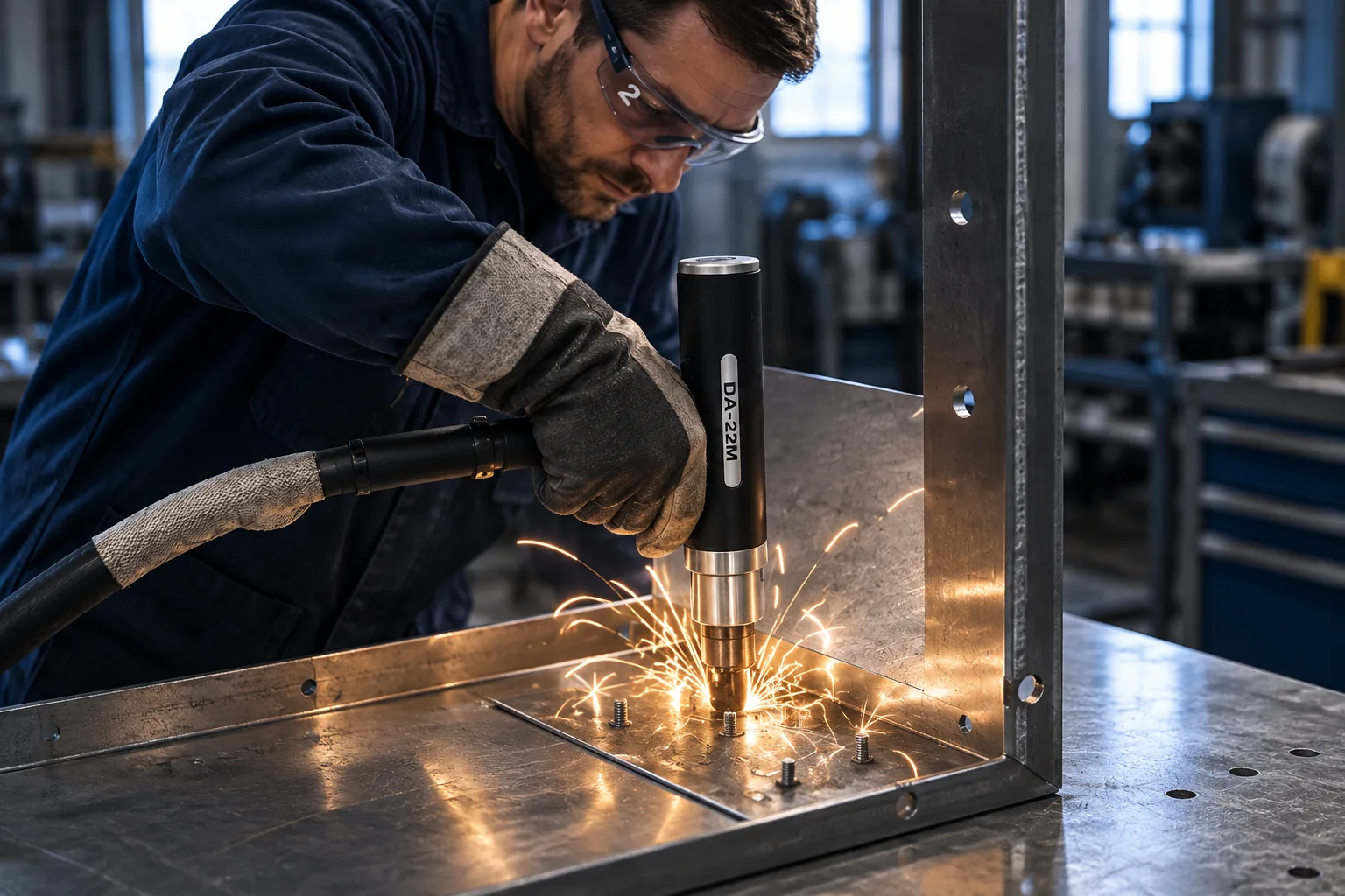
Metal fabrication
Stud welding
with drawn arc welding
Equipment for
FD welding tasks
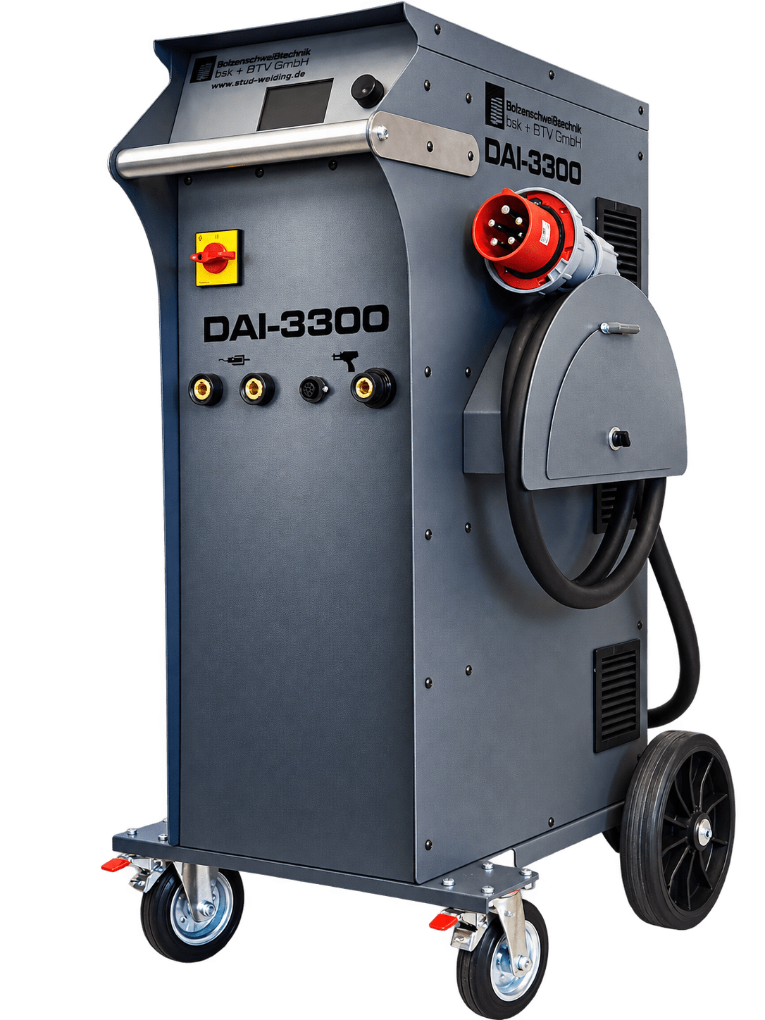
DAI-3300
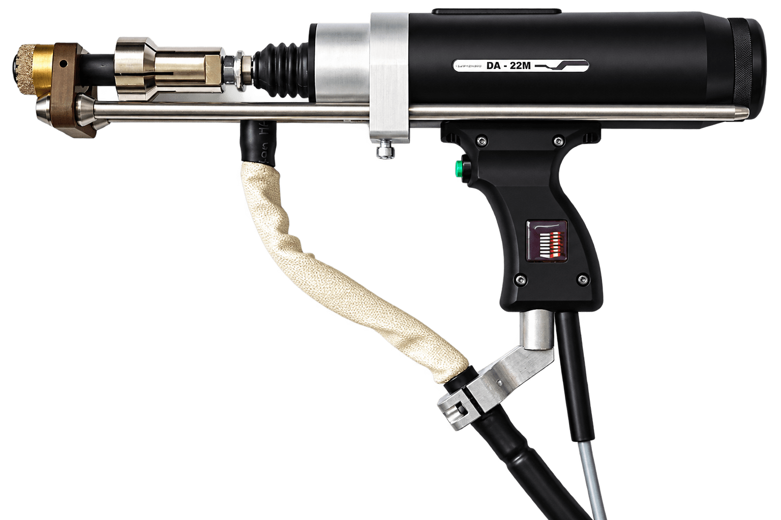
DA-22M

Automation & CNC
Frequently asked questions
about FD threaded studs
Which thread sizes and lengths does the FD data sheet list?
M6, M8, M10, M12, M16 and M20 are listed. A range of 15–100 mm is stated for l₂. The document does not identify which lengths are available in each thread size; this is clarified on request.
Which materials are documented for FD?
The product page lists steel 4.8 and stainless steel A2-50. Other materials or specific material numbers are not specified in the available FD sources.
What distinguishes an FD threaded stud?
FD is a threaded stud with a continuous external thread. The original photograph shows a flat end face and a conical welding tip.
Which process is used to weld FD?
The product source assigns FD to drawn arc stud welding. It lists manual and fully automatic processing.
How do I read the FD dimensional table?
d₁ denotes thread size. In the drawing, l₁ is length before welding and l₂ length after welding. d₃ and h₄ refer to the welding area after welding. According to the data sheet, the tip angle is 140° with a tolerance of ±7°.
Which ceramic ferrule is used for FD?
The available FD sources do not specify a ceramic ferrule type. The correct assignment and weld pool protection must be confirmed for the selected FD version.
Are DAI-3300 and DA-22M suitable for every FD?
The cards show drawn arc equipment. This does not constitute approval for every FD size. The manufacturer’s DA-22M range starts at M8; FD M6 requires a different, suitably matched gun. Please clarify equipment selection and accessories based on the welding task.
Are special versions available?
We manufacture special studs to specific requirements. Specific special lengths, additional materials or other FD versions are not defined in the available sources and are requested individually.