
The three welding processes
On this page
Capacitor discharge stud weldingShort-cycle drawn arc stud weldingDrawn arc stud welding with a ceramic ferruleWeld pool shielding with shielding gasCapacitor discharge stud welding
Capacitor discharge stud welding with tip ignition is used to weld predominantly pin-shaped metal parts approximately 1 to 10 mm in diameter onto metal sheets of various thicknesses. It is divided into two processes: contact welding and gap welding.
Contact welding
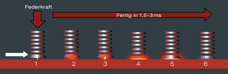
The contact process is primarily used for stainless steel and unalloyed or zinc-coated sheets (15 µm). The welding stud is inserted into the stud chuck and placed on the workpiece surface using the handheld gun or automatic welding head. A compression spring in the welding gun presses the stud, with the ignition tip characteristic of capacitor discharge stud welding, against the workpiece. Pressing the trigger on the welding gun releases the energy stored in the capacitors through a thyristor. The stud's ignition tip heats up so intensely that it melts instantaneously and partly vaporises. The resulting arc fully melts the stud end and the workpiece at the weld interface. After a welding time of only 1–3 ms and a welding current of up to 15,000 A, the stud and base material are homogeneously joined, with a very small fusion zone of just a few tenths of a millimetre. With suitable materials and coordinated welding parameters, this allows studs to be welded onto thin sheets. Whether marks or discolouration appear on the reverse side depends on the particular application.
Gap welding
The gap process differs from the contact process in that, after the trigger is pressed, a lifting solenoid in the gun raises the stud to a preset lift or gap and then a spring accelerates it towards the workpiece. As soon as the stud's ignition tip touches the workpiece, the arc ignites. Adjusting the gap changes the arc duration or welding time; this is generally shorter than in the contact process. The gap process is therefore primarily used for materials with a low melting point, such as aluminium or brass. The welding time is a maximum of 1.5 ms, and the fusion zone is even smaller than in the contact process. Particular care must be taken to ensure a clean workpiece surface free of electroplated coatings, oil, rust or scale.

Short-cycle drawn arc stud welding
Applications
Short-cycle drawn arc stud welding is primarily used for flanged studs 4 to 10 mm in diameter on thin sheets. Electroplated coatings below 30 µm are also possible. A major application is the automotive industry, where up to 600 studs are used per body-in-white.
For context: drawn arc stud welding covers pin-shaped parts 3 to 30 mm in diameter on metal workpieces of various thicknesses. This includes short-cycle drawn arc welding as well as drawn arc welding with a ceramic ferrule or shielding gas.
Welding sequence
- Insert the stud into the stud chuck of the welding gun or automatic welding head. Support the gun on the workpiece using a positioning tube, support foot or shielding gas attachment.
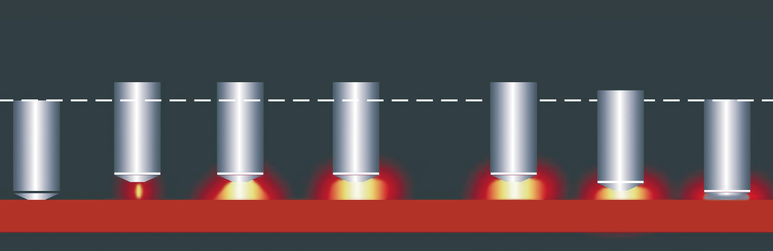
- After triggering, a lifting solenoid lifts the stud away from the workpiece. A pilot arc is ignited.
- The welding power source switches on the main current. The arc melts the stud end and the workpiece surface.
- At the end of the preset welding time, the lifting solenoid releases. A spring presses the stud into the molten weld pool.
Technical parameters
- Welding time is matched to the material and application.
- Welding current: 500 to 1,500 A, depending on the application and stud diameter
- Fusion zone: approximately one eighth of the stud diameter
Drawn arc stud welding with a ceramic ferrule
Applications and parameters
Drawn arc stud welding with a ceramic ferrule is mainly used in structural steelwork and mechanical engineering. Threaded or headed studs 6 to 25 mm in diameter are welded onto thick steel plates or beams.
- Workpiece thickness: greater than one quarter of the stud diameter
- Welding time: 100 to 1,000 ms
- Welding current: 800 to 2,600 A
Purpose of the ceramic ferrule
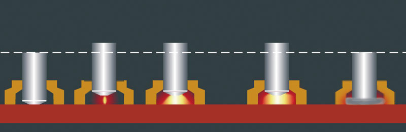
The ceramic ferrule shapes the weld pool, stabilises the arc and shields the welding location from the surrounding atmosphere. An aluminium ball pressed into the centre of the stud's conical end acts as a flux and deoxidiser.
After welding
Each ceramic ferrule is used for one weld only. After the molten metal has solidified, the ferrule is removed by breaking it away from the stud.
Weld pool shielding with shielding gas
This process can be extended by using shielding gas, or shielding gas can replace the ceramic ferrule. This significantly reduces porosity in the molten metal and produces a more attractive fillet-shaped weld collar. For suitable steel applications, a mixture of 82 % argon and 18 % CO₂ can be used. We use pure argon for drawn arc stud welding of aluminium. Gas selection depends on the material and welding process; the gas is supplied through an appropriate shielding gas attachment on the welding gun. Welding time, welding current and suitable stud dimensions depend on the material and application. The process is matched to the sheet thickness.

