
GAP
AI
TECHNICAL DATA
M3–M10
Ø 11 mm
0.85 kg
3 m
25 mm²
1.0–4.0 mm
GAP OR GAP-M?

Capacitor discharge using the gap method
The gap method sequence
The stud is first lifted and then moved towards the workpiece. When the ignition tip makes contact, the capacitor energy is released. The arc melts the stud end and workpiece surface. The stud plunges into the weld pool.
More about stud welding processesLift the stud
The stud is lifted from the workpiece before ignition. The lift is adjusted on the gun from 1.0 to 4.0 mm.
Ignite the arc
The stud moves towards the workpiece. When the ignition tip makes contact, the capacitor energy is released; the ignition tip melts and an arc forms.
Plunge the stud
The stud plunges into the weld pool. The stud and base material solidify to form a joint.
Features
Standard version
Continuously adjustable lift
Linear ball guide
Thermoplastic housing
Welding current cable
Mechanical design
APPLICATIONS & MATERIALS
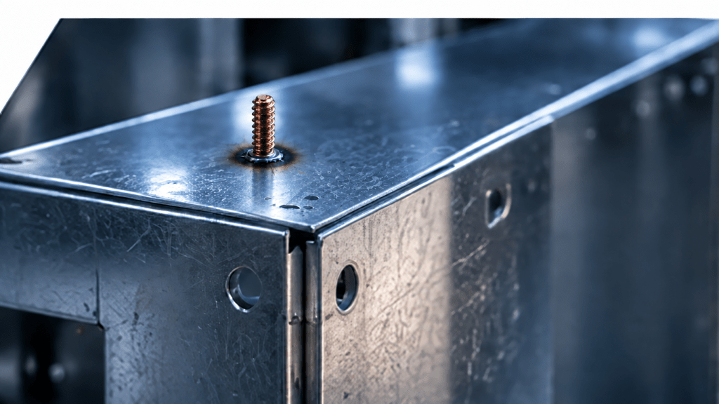


 AI-generated · example

 AI-generated · example
GAP and CDP-M power units
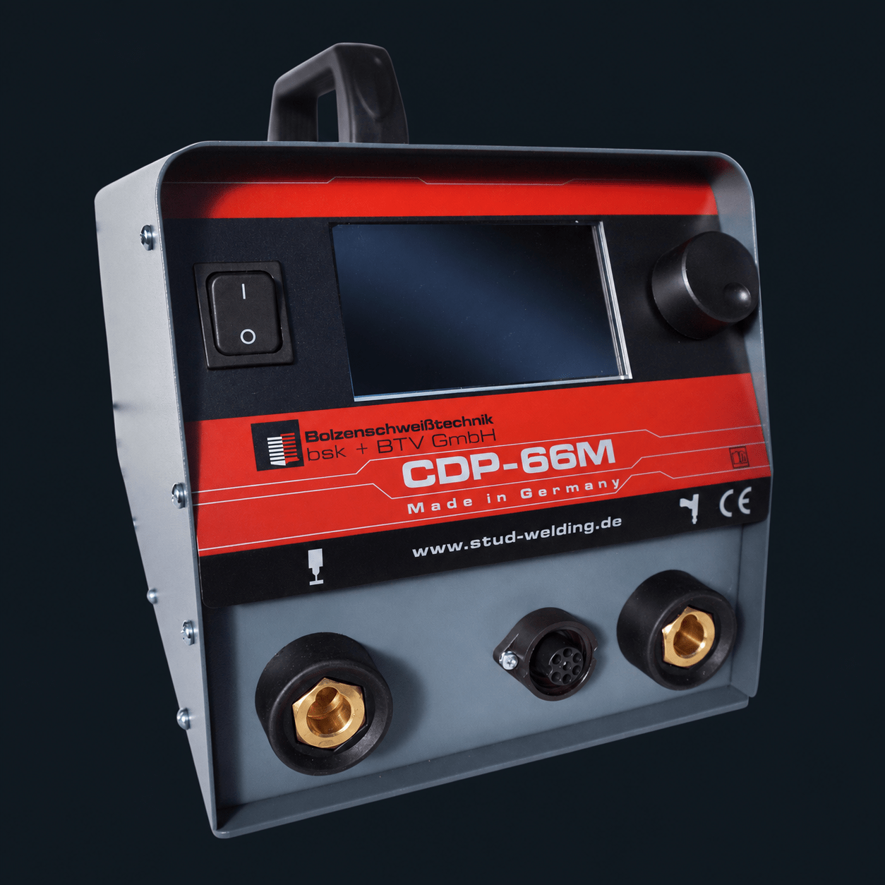
CDP-66M
Compact power unit for capacitor discharge applications and steel or stainless steel studs up to M8.
- Displacement measurement only with a separate M gun
- Stud range M3 to M8
- 4-inch graphic display

CDP-99M
Power unit for capacitor discharge applications up to M10 with optional process monitoring and multi-station technology.
- Displacement measurement only with a separate M gun
- Stud range M3 to M10
- Optional Switch-4
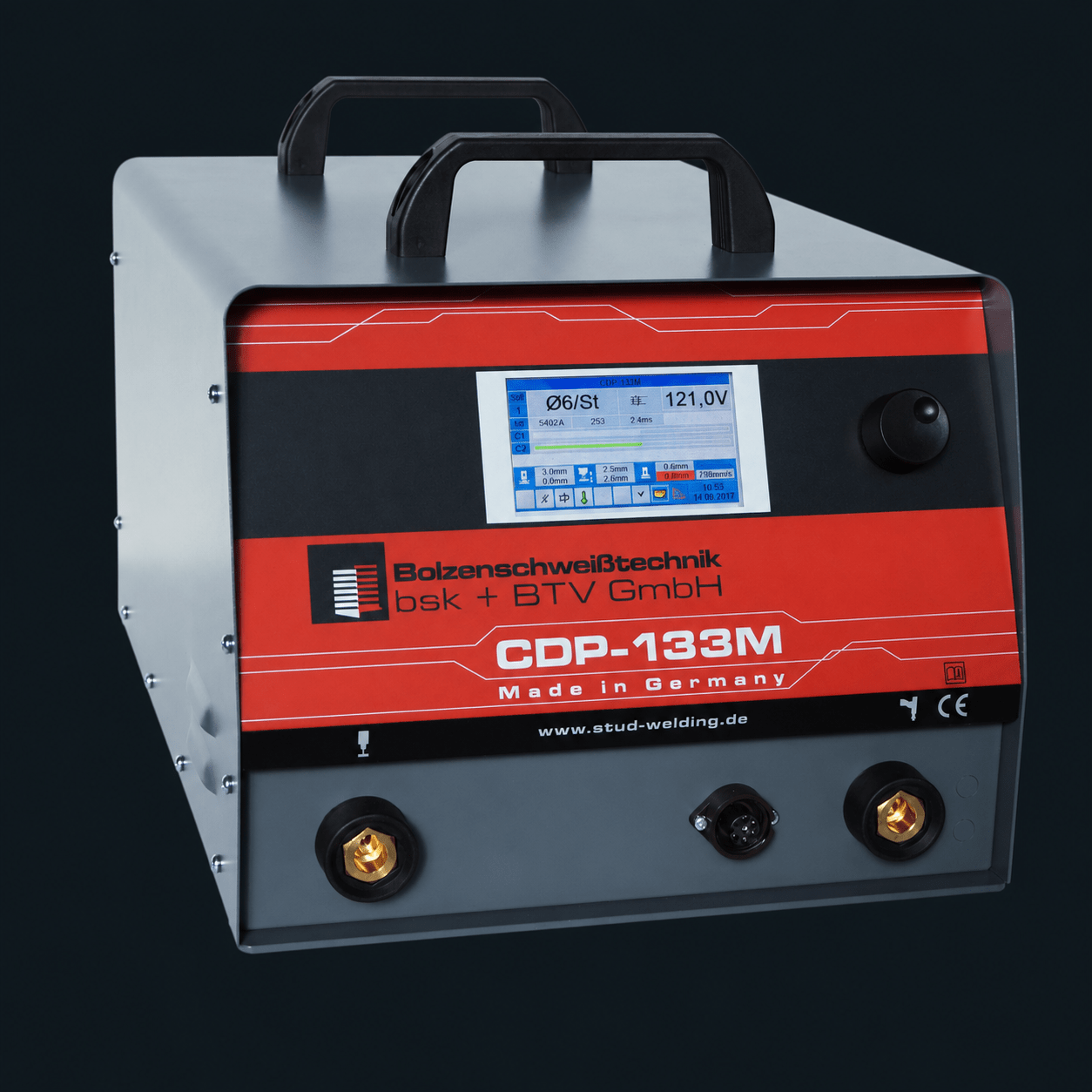
CDP-133M
High-performance CDP-M version with switchable capacitance for demanding manual and automated applications.
- Displacement measurement only with a separate M gun
- Stud range M3 to M10
- Optional process monitoring
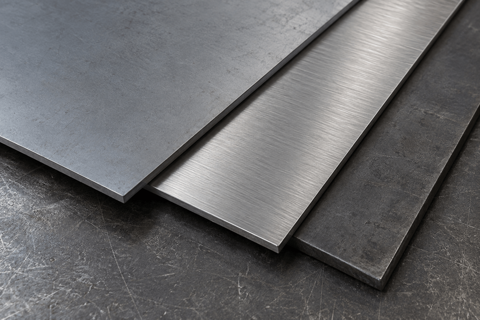
SUITABLE MATERIALS

For capacitor discharge welding using the gap method
Non-heat-treatable aluminium alloys

M3–M10, maximum Ø 11 mmThe usable welding range depends on the power unit, material and welding task.
COMPATIBLE WELDING ELEMENTS

The GAP in detail
| Gun type | GAP |
|---|---|
| Welding process | Capacitor discharge, gap method |
| Applications | Unalloyed and alloyed steels, and non-heat-treatable aluminium alloys |
| Welding range | M3 to M10, maximum Ø 11 mm |
| Guide | Linear ball guide |
| Displacement measuring system | Not integrated; displacement measurement only with GAP-M |
| Lift adjustment | 1,0–4,0 mm, continuously adjustable using the scale on the gun |
| Vertical alignment | Manual alignment without a circular spirit level |
| Length compensation | Not fitted |
| Plunge damping | Not fitted |
| Welding current cable | 3 m / 25 mm² |
| Housing material | Glass-fibre-reinforced thermoplastic |
| Weight without cables | 0.85 kg |
Technical documents
Still unsure which option to choose?
Find the right solution for your application.
START SOLUTION FINDERFrequently asked questions
about GAP
Which process does GAP use?
The GAP uses capacitor discharge stud welding with tip ignition using the gap method.
What welding range is possible?
The GAP welding range is M3–M10, with a maximum diameter of Ø11 mm. The usable range depends on the power unit, material and welding task.
Which materials are intended?
The gun is designed for alloyed and unalloyed steels, and non-heat-treatable aluminium alloys.
How is the lift adjusted?
The lift is continuously adjusted from 1.0 to 4.0 mm using the scale on the gun.
Does GAP have integrated displacement measurement?
No. GAP is the standard version without a displacement measuring system. GAP-M also enables the mechanical welding parameters to be recorded.
Which power units are compatible?
The GAP is compatible with CDP-66M, CDP-99M and CDP-133M power units.
For different components and welding positions
Accessories and spare parts for GAP/GAP-M are listed in the manual spare parts catalogue. The choice depends on the gun model, welding element and installation conditions. Please specify the GAP version when making an enquiry.
- Accessories to suit GAP/GAP-M
- Spare parts by model and version
- Selection according to welding element and application

