
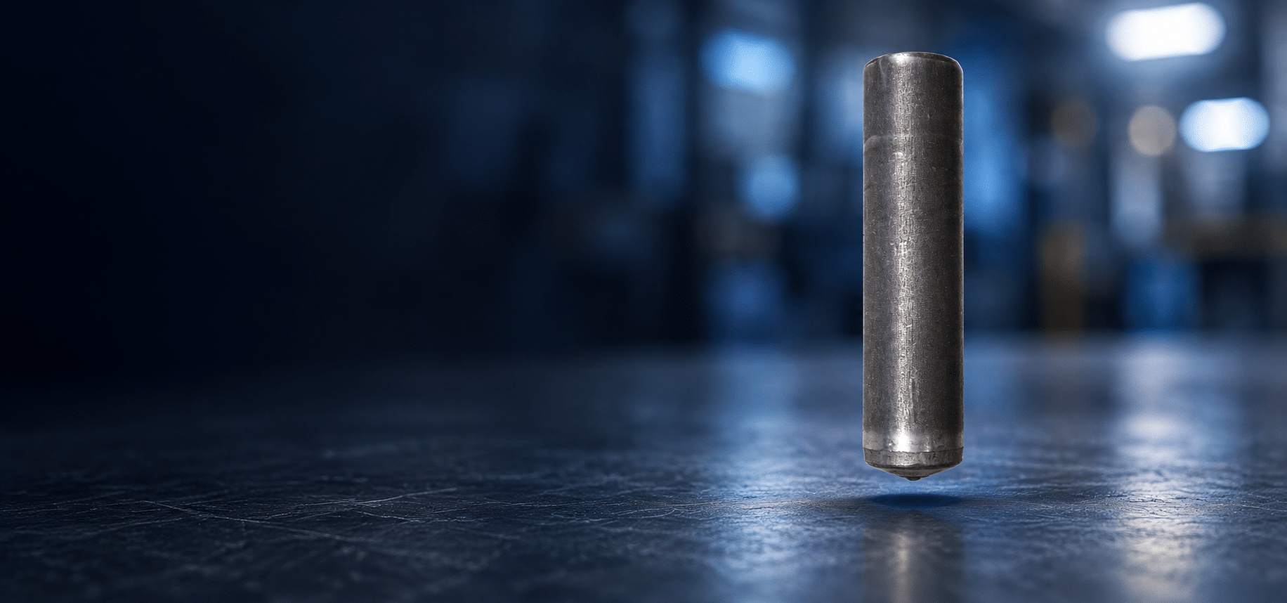
PIN
UD
SMOOTH SHANK.
WELDABLE JOINT.

| Welding process | Drawn arc welding |
|---|---|
| Diameter | Ø 6–16 mm |
| Standard reference according to the data sheet | DIN EN ISO 13918:2018 |
| materials | Steel 4.8 · stainless steel A2-50 |
| Ceramic ferrule | UF with aluminium flux |
| Shielding gas | Without aluminium flux up to Ø 10 mm |
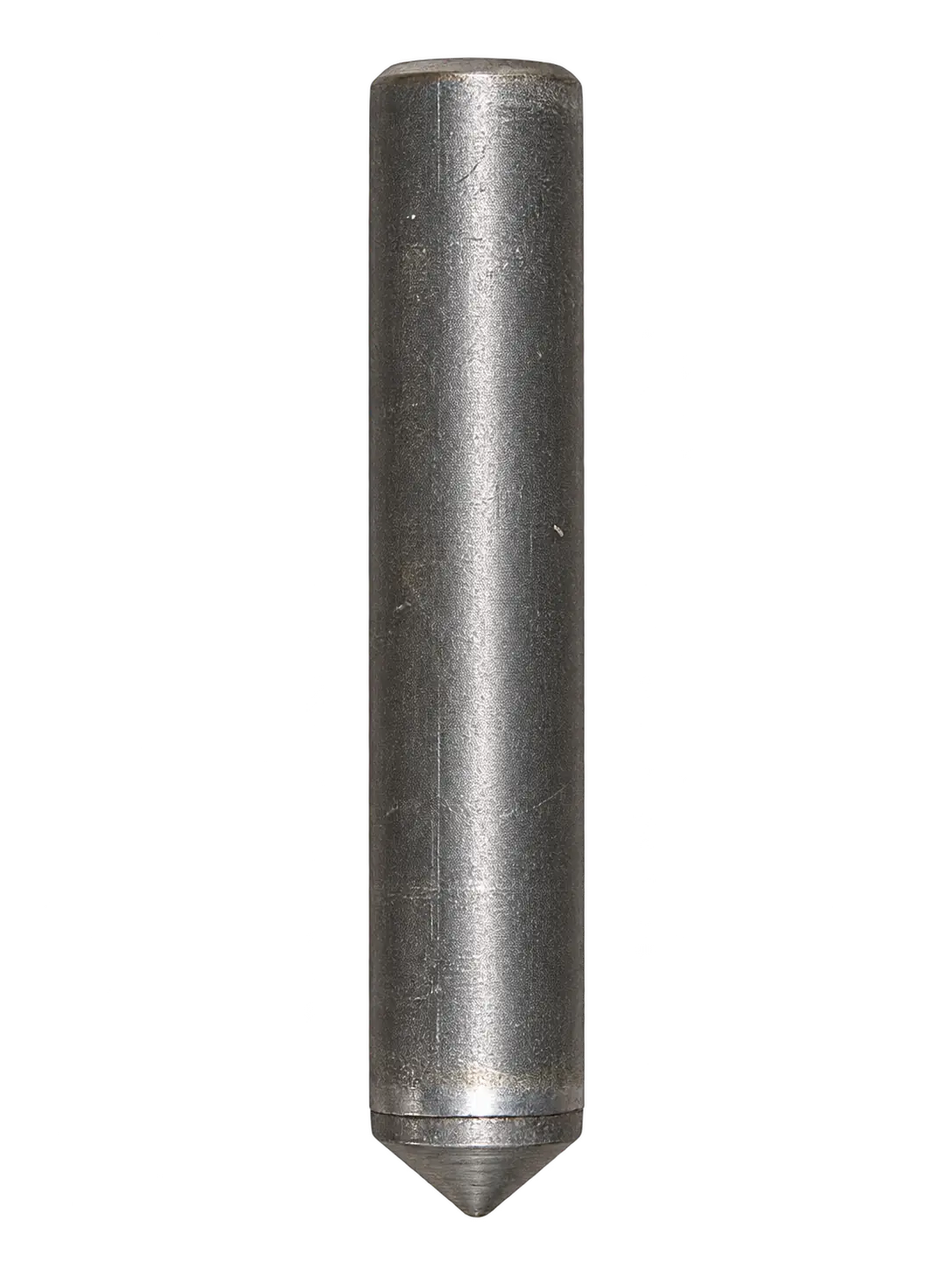
UD pin: shape and version
UD: dimensions
and materials
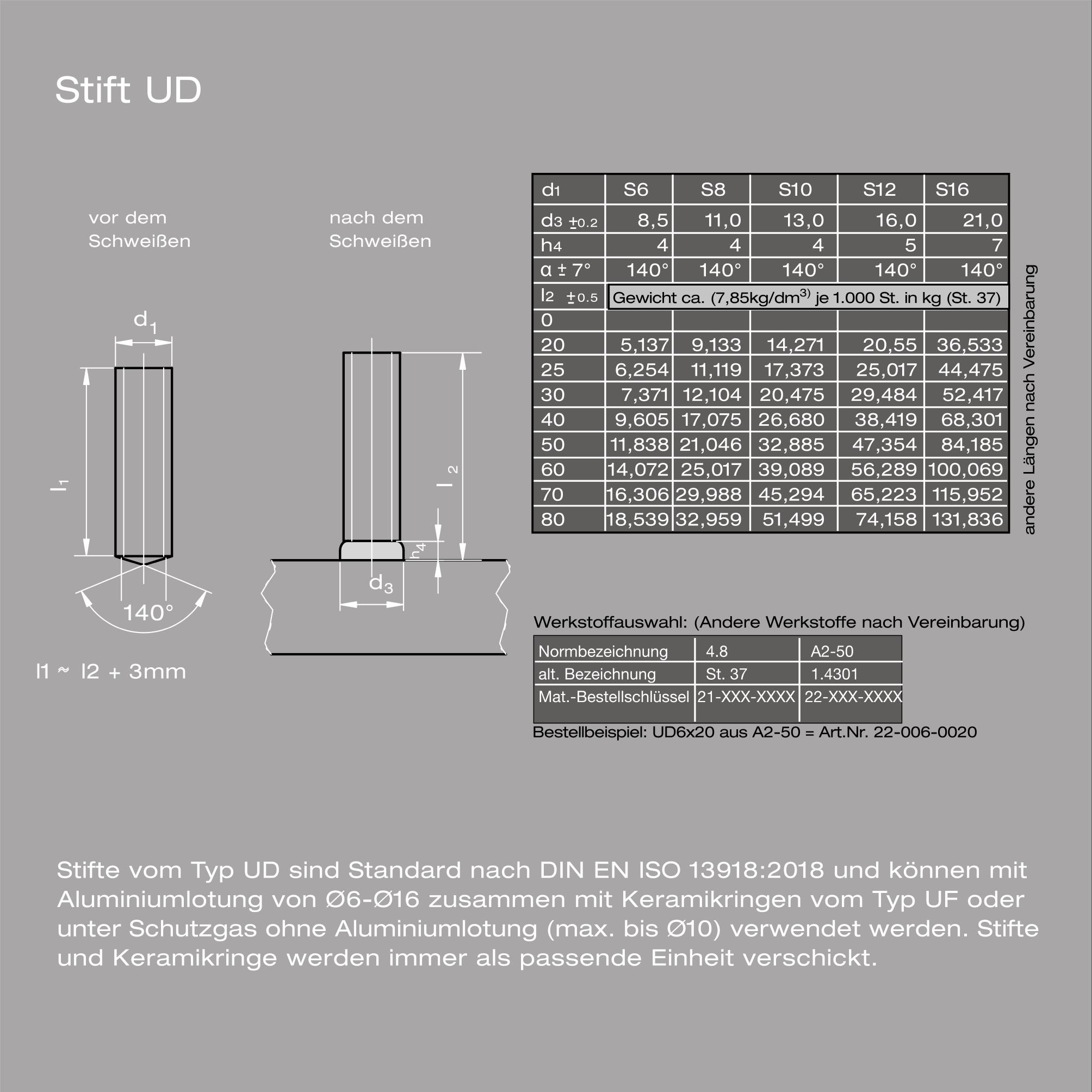
| d₁ | d₃ | h₄ |
|---|---|---|
| S6 | 8,5 | 4 |
| S8 | 11,0 | 4 |
| S10 | 13,0 | 4 |
| S12 | 16,0 | 5 |
| S16 | 21,0 | 7 |
d₃ ±0.2 mm; l₂ ±0.5 mm; α = 140° ±7°. l₁ ≈ l₂ + 3 mm.
| d₁ | l₂ in mm |
|---|---|
| S6 | 20, 25, 30, 40, 50, 60, 70, 80 |
| S8 | 20, 25, 30, 40, 50, 60, 70, 80 |
| S10 | 20, 25, 30, 40, 50, 60, 70, 80 |
| S12 | 20, 25, 30, 40, 50, 60, 70, 80 |
| S16 | 20, 25, 30, 40, 50, 60, 70, 80 |
*The listed lengths 20–80 mm are documented in the data sheet for all five diameters. Other lengths by agreement. Blank data sheet fields are not interpreted as available combinations.
| Material | Class | Designation in the sheet | Code |
|---|---|---|---|
| Steel | 4.8 | St. 37 | 21-xxx-xxxx |
| Stainless steel | A2-50 | 1.4301 | 22-xxx-xxxx |
Ordering example according to the data sheet: UD6×20 in A2-50 → article no. 22-006-0020.
UD pins
for industrial tasks
Structural steelwork

Vehicle manufacturing

Mechanical engineering

Plant engineering

Rail vehicles
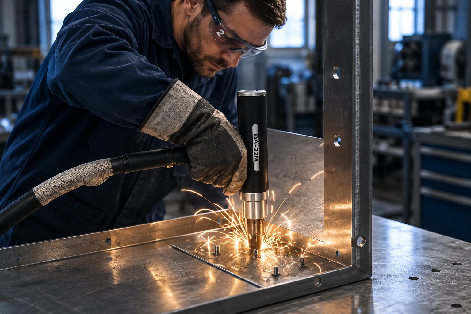
Metal fabrication
Stud welding
with drawn arc welding
Equipment for
UD welding tasks
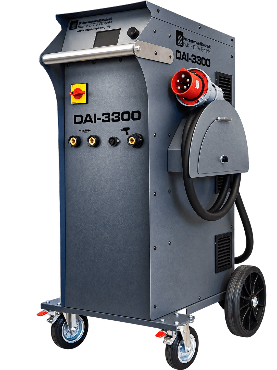
DAI-3300
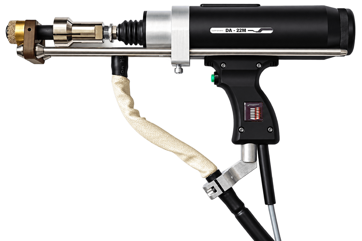
DA-22M

Automation & CNC
Frequently asked questions
about UD pins
Which sizes and lengths are documented?
The data sheet lists Ø 6–16 mm and an overall l₂ range of 20–80 mm. The table shows only combinations with an entry in the manufacturer’s sheet. Other lengths and current availability are clarified on request.
Which materials are offered?
Steel 4.8 and stainless steel A2-50. The data sheet also lists St. 37 and 1.4301 respectively; other materials by agreement.
What distinguishes the design?
The original photograph shows the unwelded pin with a smooth shank and conical welding tip. The data sheet lists five diameters from 6 to 16 mm. Steel 4.8 and stainless steel A2-50 are specified as materials.
Which welding process is used?
Drawn arc welding – manual or fully automatic. With aluminium flux and UF ceramic ferrules for Ø 6–16 mm; under shielding gas without aluminium flux only up to Ø 10 mm according to the source.
How do I read the dimensional table?
l₁ denotes length before welding and l₂ length after welding. d₃ and h₄ describe the weld collar area. d₃ ±0.2 mm; l₂ ±0.5 mm; α = 140° ±7°. l₁ ≈ l₂ + 3 mm.
Which ceramic ferrule is used for the product?
The manufacturer specifies type UF. The ferrule and element must be selected to match the size and application. A separate original photograph and ferrule dimensions are not available in the supplied documents.
Is every illustrated item of welding equipment suitable for all sizes?
No. The cards show examples of drawn arc equipment. A complete approval matrix for all UD sizes and materials is not available. The unit, gun, welding head, holder and weld pool protection are selected for your task.
Are other lengths or special versions possible?
We manufacture special studs to individual requirements. Send the size, required length, material, quantity and, where applicable, a drawing. The specific version is reviewed.


